A New Design
The problems with the further development of No. 8 were discussed in detail with locomotive owner Alan Richardson. He felt that a more satisfactory approach would be to leave No. 8 as a working locomotive and to produce a new design tailored to the current and future operating needs of the BVR. He therefore ask Alan Keef Ltd and I to carry out a design study for the new locomotive and this is described below.
The new design takes shape
Taking the performance of No. 9 as a baseline for reference, the philosophy behind this new design is to provide improvements in the operating characteristics to meet the BVR’s current and future needs at the lowest total cost of ownership.
A number of areas were specifically targeted as priorities. Firstly, we wanted to provide a small increase in available power to facilitate the handling of heavy trains or the recovery of lost time by quick acceleration and also to increase the adhesion so that the extra power could be usefully applied to the rail. In conjunction with this we also wanted to improve the thermal efficiency and reduce operating costs by further reductions in fuel and water consumption in service. Secondly, the tasks of locomotive preparation, operation and disposal could be reduced by making items such as inspection, lubrication and cleaning as straightforward and easy as possible for the engine crew. Similarly availability could be increased and costs reduced by making routine maintenance and servicing as convenient as possible for the engineering staff and by using proprietary or stock items for consumable parts wherever possible. Lastly, we designed for ease of manufacture, to minimise the initial cost of construction, but without compromising the required operating characteristics.
A tank locomotive type was chosen as it is ideal for short haul work. There is sufficient space on the locomotive to carry the required fuel and water and these contribute to the available adhesive weight and avoidance of a tender maximises the power to weight ratio. For example No. 9, which is a tank locomotive, has a power to weight ratio of 11.3 drawbar hp/tonne but No. 6 which is identical, apart from having a tender, has a power to weight ratio of 9.41 drawbar hp/tonne. The new design will achieve a still higher power to weight ratio of 13.3 drawbar hp/tonne. Additionally, the capital cost of the locomotive is minimised as there is no tender to build and maintenance costs and overall availability are improved as there is less to maintain.
The 2-8-0 wheel arrangement was selected to enable a fourth driving axle to be used. This means that the maximum axle load of No. 9 is not exceeded, which will be kind to the track, while the adhesion factor in full operating condition is still improved from 4.1 for No. 9 to 5.8 despite an increase in power. Additionally, the absence of trailing non-coupled wheels avoids the transfer of weight from the driving wheels that occurs when pulling hard thus ensuring that the locomotive is less likely to slip. Lastly, the longer wheelbase compared to the overall length of the locomotive will give good longitudinal stability in the transverse plane which will be kind to the permanent way.
Despite the stalwart efforts of the BVR permanent way department, the selection of round shingle rather than crushed granite as ballast by the original builders of the line makes it difficult to maintain alignment and levels. Sleepers sitting on ‘ball bearing ballast’ soon move with temperature changes and the passage of trains and therefore the design will feature fully compensated suspension to improve adhesion of the locomotive on areas of uneven track. Elastomeric springs made from moulded rubber will be utilised throughout to avoid the possibility of fatigue failures associated with the use of more vulnerable leaf springs and elastomeric bump stops will also be used to control the maximum travel of axleboxes. As an additional aid to stability and improved ride the leading pony truck is also coupled to the compensated suspension. In this arrangement, not only does the truck self-centre using roller followers acting on inclined planes, but as the axle is displaced laterally the locomotive will lean slightly into a bend.
Air operated sanding gear will be provided with the dry sand being stored in a box formed as part of the frames in the area of the apron plate. This position should ensure that, providing any spills are swept off, none should blow or fall into the motion. The sand will be applied ahead of the leading driving axle and provision will be made to ensure the sanders can be easily unblocked by the engine crew if the sand becomes damp.
The boiler design will differ from the ZB arrangement in that the barrel will be 200 mm larger in diameter at 800mm and have a six flue superheater. Although the grate area will be the same at 0.37 sqm the firebox is of a narrow design with a sloping grate over the rear driving wheels. This will ensure that the boiler is well supported and the overhang at the rear of the engine is minimised giving good weight distribution and reducing the tendency to yaw laterally where rail joint alignment is poor.
The firebox arch will be made in two parts from stainless steel as it can be thinner than a cast refractory arch and this will provide additional height for coal on the grate at the front of the firebox. A stainless steel deflector plate and horizontally hinged mild steel fire door will optimise the admission of secondary air to aid good combustion. The locomotive will have a single chimney and a four nozzle Lempor exhaust system, similar to that used on No. 9, to keep exhaust back pressure to a minimum.
Coal firing was chosen for reasons of lower capital and operating cost and with the reduced tendency to create sparks demonstrated by No. 9 it was felt unnecessary to consider oil firing. The coal bunker is integral with the rear of the water tank on the fireman’s side, with a shovel plate at footplate level. The top of the bunker has a sealed lid to prevent dust being blown into the cab due to air flow through the fuel when running forward and the total coal capacity is approximately 140 Kg. Despite the slightly asymmetric transverse loading which occurs with this arrangement this was preferable to the overhung weight at the rear of the engine which occurs with a bunker of the type fitted to No. 9.
The high running plate was chosen to make access to the motion easy for maintenance and operating purposes. Optionally a rocking grate and hopper bottomed smokebox could be included to make preparation and disposal less labour intensive. All the motion and axlebox bearings are to be roller bearings as this not only makes lubrication a simple once a day activity but also reduces the internal resistance of the locomotive.
All rotating masses of the motion will be fully counterbalanced and reciprocating masses will be partially counterbalanced to approximately 33% of their mass to minimise longitudinal oscillations at the drawbar which currently can be a problem with the ZBs.
Thermal efficiency and power output will be increased by the use of thicker ceramic boiler insulation, moderate superheating to an average of 100° C over the operating range, a small increase in boiler pressure to 200 psi and a slight reduction in driving wheel diameter from 610 mm to 550 mm to increase piston speed.
The cylinders will be the proven design used on No. 9 with some small detail design changes to accommodate the increased power and superheating. The transfer ports in the valve liners will be lengthened to increase the area to allow for additional power output when using long cut-offs at maximum line speed and there will be a small increase in the lead steam to help cylinder filling at the slightly higher maximum revs required by the smaller driving wheels.
Our estimates indicate that the power output will be increased by approximately 24% compared with No. 9 for an equivalent quantity of fuel consumed and that the maximum drawbar horsepower available will be around 140 hp at 20 mph which should make for some exciting traction! Alternatively, if the power output is controlled in service to match that typically provided by No. 9, savings of approximately 20.4% in fuel and 23.5% in water will be made.
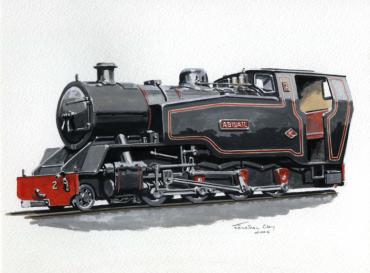
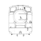
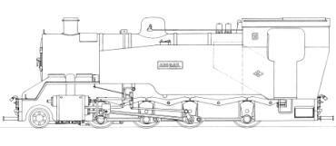
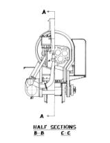
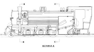
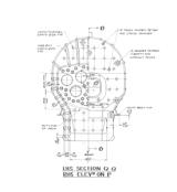
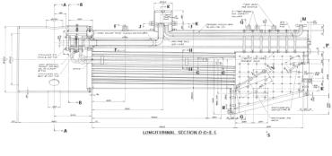
Computer modelling has been used to assess the key parameters and design layout drawings of both the locomotive and boiler have been prepared to ensure that reality will reflect our theories! The resulting design is a visually attractive modern locomotive, readily appreciated from the wonderful painting by transport artist, Jonathan Clay, prepared from the engineering drawings and reproduced above.
The design study has shown that this project for an attractive high performance 15" gauge locomotive is feasible and we are looking forward to the realisation of the proposal in the future.
For information about the organisations mentioned in this article, see the Links page.
