The New Front End
As a Consultant Design Engineer by profession I had undertaken projects previously with the owner of BVR No. 9 'Mark Timothy', Alan Richardson, and he invited me to design a new front end for the locomotive to improve power output and fuel economy. Concurrent with the commencement of the rebuilding of No. 9 the BVR were rebuilding No. 6 and this led to the possibility of designing and building new cylinders and draughting arrangements for both locomotives unhampered by the legacy of the existing parts.
A project of this nature is always the subject of collaboration between the interested parties and I would like to especially mention the workshop teams of both the BVR and Alan Keef Ltd who contributed their expertise to the programme.
Redesigning the front end
Designers like Chapelon, Porta and Wardale advocate that design must progress considering the locomotive as a whole and with a clear understanding of the thermodynamic implications so that the technical potential of improvements can be assessed. Whether a potential improvement is commercially worthwhile must then be judged in the context of total cost of ownership and with locomotives of this size the relative balance of the various contributions is different compared to say standard gauge locomotives with different usage patterns.
In this case, despite the thermal efficiency benefits obtainable by superheating, modification of the boilers was ruled out at this stage for financial reasons as it would have meant replacing large parts of sound boilers and the fuel saving could not justify the costs involved. However, consideration was given to possible fitment of superheated boilers at some point in the future when replacement was required. Similarly, to limit the impact of the work on the rest of the locomotive, the mainframes were not to be modified and the existing cylinder mounting bolt positions, exhaust passageway cut-outs and cylinder bore and stroke were retained.
Accepting that it was to remain a saturated engine, the important point with the new front end design was still to get more useful work out of the steam before exhausting it. To do this required both expansion of the steam to the lowest pressure possible to maximise the useful work done and also minimising negative work in the form of back pressure, friction and avoidable leakage and condensation losses.
With this in mind I prepared an outline design scheme and, having obtained everyone’s approval, undertook the necessary computer modelling, design calculations and drawings to enable manufacture of the parts for both locomotives.
Looking at the improvements in broad terms and working through the items in a logical sequence we start at the cylinder steam chests.
To meet the demand at speed when the valve opens during admission you need large steam chests so that sufficient steam is available. This ensures that steam pressure doesn’t fall because it suddenly has to surge down the steam pipe from the boiler to get there. For this reason the steam chests were made as big as possible within the constraints of the loading gauge and while the volume is a little smaller than is ideal they are more than eight times larger than the originals.
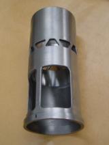
The valves and ports are also important in controlling the steam flow to and from the cylinder and the transfer ports were designed with fewer but larger trapezoidal shaped ports to improve the available area during initial opening compared to the smaller but more numerous triangular form used previously. The use of narrow tapered lands on the admission and exhaust edges of the valve head enabled the valve events to be defined accurately by the valve rings under the control of the valve gear.
The valve gear was redesigned to improve the valve events by correcting geometry errors and limiting the full gear cut-off from 82% to 70% while also increasing the maximum valve travel by 10 mm to 74 mm. The overall effect is to make port openings larger for a given cut-off and is coupled with generous radii on the valve head which smooths the passage of the steam adjacent to the port.
Back pressure is minimised by allowing some of the exhaust steam to pass through the hollow valve head to make use of the other exhaust passageway branch. The combined effect of these changes is to promote good breathing while also reducing loads on the valve gear by lightening the valve head and balancing the load created by the exhaust back pressure.
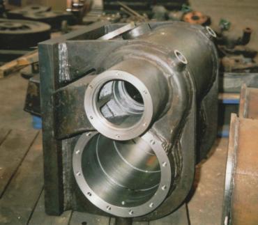
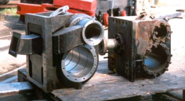
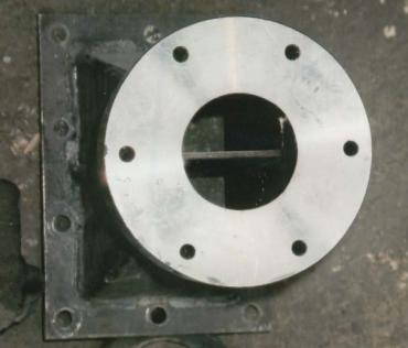
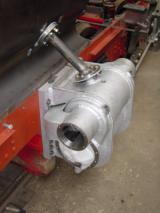
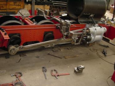
The transfer passageways between the valve chest and cylinders and the exhaust passageways have also been carefully designed with rectangular sections to maximise the area for flow. They are as straight as possible but, where necessary, bends are flowing and even the valve chests and cylinders are smoothed internally. Compared to the original arrangement the passageways are enormous and one look at the illustration shows the difference in size between the original cylinders and the replacement units.
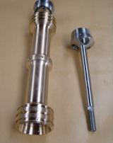
Sealing of the valves and piston has been improved by using Clupet rings which are shaped rather like a key ring and have no gap between the ring ends for steam to leak through. In addition the valve heads now have three rather than two ring grooves as the increase in lap has created enough space to fit them. The valve head is made of bronze giving good wear characteristics in combination with the cast iron valve liner and is supported by a tail rod to improve guidance.
Avoidable heat loss has been lowered by the use of better and thicker ceramic insulation and reduction of contact area between the main frames and cylinders. Heat loss is further minimised by arranging for all coasting to be done in mid-gear as this prevents cooling of the cylinders by cold ambient air drawn in through the snifting valves. To enable mid gear coasting, without abrasive smokebox combustion gas and ash being drawn into the cylinders via the blast pipe, requires the provision of a small quantity of steam to the steam chest. By using this steam to atomise the cylinder lubricating oil as it enters the steam chest the lubrication of valves and pistons is also improved.
Better expansive use of the steam can now be made as a result of the improved valve events and with a small clearance volume a maximum expansion ratio of 4.26 is achievable at 15% cut-off.
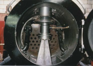
The draughting arrangements in the smokebox were improved by the fitment of a multiple blast nozzle Lempor exhaust system which creates sufficient draught for efficient combustion with lower exhaust back pressure. A Kordina was also incorporated in the exhaust passageways from the two cylinders where they combine below the blast nozzles. This device prevents the exhaust release from one cylinder increasing the back pressure in the second cylinder.
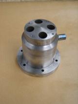
The four nozzle blast cap is effectively 44.5% larger than the original single nozzle blast pipe taking into account the improved flow coefficients and has an integral four nozzle blower. This was machined rather than fabricated because of the small physical size and accuracy required which made this the easiest option. The Lempor mixing chamber and diffuser is concealed within a chimney of classical external shape but is larger in diameter as the exit area of the chimney was increased by 123% compared to the original. A further benefit is that the revised layout distributes the draught more evenly across the boiler tube plate and it is hoped that this will reduce the incidence of tube leakage in service from the upper rows of boiler tubes.
Rebuilding gets underway
During the later half of 2002 work got underway in earnest at Alan Keef’s works. Under the supervision of works manager Phil Kent, the frames were lengthened and strengthened at the front and rear to suit the new design. During this period the pony truck and rear bogie were extensively rebuilt to provide adequate movement and side control. The successful 'shoe horning' of the alternator and rotary air compressor onto the rear bogie was particularly difficult with very limited space.
While the boiler was removed from the frames the opportunity was taken to carry out minor remedial work on it. The washout sockets, dome and one longitudinal stay which had curiously been found to be welded in position under compression all receiving attention.
Meanwhile, engineer Alice Keef had been looking at the typical weight distribution of the ZB design and confirmed that it was excessively back heavy. To correct the balance it was decided to fit a heavier front buffer beam and make the smokebox from 40 mm instead of the usual 6-10 mm thick plate. Alice is confident that this is one smokebox which is never going to rust through!
New coupling rods were designed by Alice to clear the lower running boards required by the new Leek and Manifold outline and Phil and his team in the works made these items along with replacement or remedial work on nearly every other item of the motion and valve gear.
As work on the chassis progressed, attention turned to the design and fabrication of the new tanks, bunker and cab. The tanks and bunker were fabricated first and then a wooden mock-up of the cab was prepared to check the sightlines and positions of controls and equipment before finalising the drawings for construction.
The new cab is extremely spacious and is fitted out to a very high standard internally with opening windows, a sunroof, and a wooden lining to the cab roof from which is suspended an instrument binnacle with integral LED spot lights for illumination of gauges. This is definitely the loco for winter nights on Santa trains!
The article continues with part three: Commissioning Trials.
